7 Segment Display + Multiplexing
A tutorial on how to use the 7 segment display with the Raspberry Pi Pico
YouTube Video
A 7-segment display is an electronic device that is used to display numeric information in a digital format. It consists of seven LED (Light Emitting Diode) segments arranged in a rectangular shape, with an eighth segment for displaying decimal points. Each of the seven segments can be lit up individually, allowing for the display of numbers 0 through 9, as well as some letters and symbols.
The 7-segment display is commonly used in digital clocks, calculators, and other electronic devices that require numeric displays. It can be interfaced with a microcontroller or other digital device, and controlled using simple digital signals.
There are two types of 7-segment displays: common anode and common cathode. In a common anode display, all the anodes of the LEDs are connected together and to a positive voltage source, while each of the cathodes is connected to a digital output pin. In a common cathode display, the cathodes of the LEDs are connected together and to a negative voltage source, while each of the anodes is connected to a digital output pin.
To display a number on the 7-segment display, the appropriate digital outputs are turned on or off, causing the corresponding segments to light up.
Overall, the 7-segment display is a versatile and widely-used display module that provides a simple and effective way to display numeric information in a digital format. Its ease of use and low power consumption make it a popular choice for hobbyists and professionals alike.
Components Needed
| Component | Quantity |
|---|---|
| Raspberry Pi Pico W | 1 |
| Micro USB Cable | 1 |
| Breadboard | 1 |
| Wires | Several |
| Resistor | 1 - 300Ω |
| 7 Segment Display | 2 |
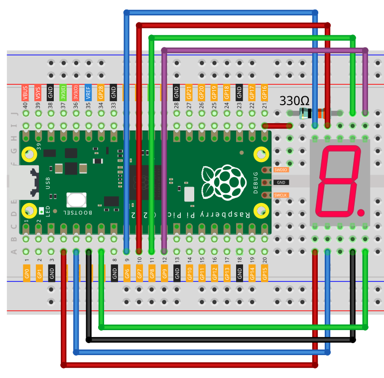
Example 1 - Fritzing Diagram
Code
from machine import Pin
import utime

# Define the GPIO pins for each segment
segments = (8,9,4,3,2,7,6,5)

# Define the digit patterns for 0-9 on the 7-segment display
# 0 means the segment is on, 1 means the segment is off
patterns = [
    (0, 0, 0, 0, 0, 0, 1, 1),  # 0
    (1, 0, 0, 1, 1, 1, 1, 1),  # 1
    (0, 0, 1, 0, 0, 1, 0, 1),  # 2
    (0, 0, 0, 0, 1, 1, 0, 1),  # 3
    (1, 0, 0, 1, 1, 0, 0, 1),  # 4
    (0, 1, 0, 0, 1, 0, 0, 1),  # 5
    (0, 1, 0, 0, 0, 0, 0, 1),  # 6
    (0, 0, 0, 1, 1, 1, 1, 1),  # 7
    (0, 0, 0, 0, 0, 0, 0, 1),  # 8
    (0, 0, 0, 1, 1, 0, 0, 1)   # 9
]

# Initialize the GPIO pins
pins = [Pin(seg, Pin.OUT) for seg in segments]

# Initialize the common cathode for the display
display = Pin(16, Pin.OUT, value=1)

def display_digit(digit):
    # Get the pattern for the digit
    pattern = patterns[digit]

    # Set each segment to the correct state
    for i in range(8):
        pins[i].value(pattern[i])

    # Turn on the display
    display.value(0)

    # Turn off the display
    display.value(1)

# Test the display
while True:
    for i in range(10):
        start = utime.ticks_ms()
        while utime.ticks_diff(utime.ticks_ms(), start) < 1000:
            display_digit(i)
Code explanation
GPIO Pin and Digit Pattern Definitions
from machine import Pin
import utime

# Define the GPIO pins for each segment
segments = (8,9,4,3,2,7,6,5)

# Define the digit patterns for 0-9 on the 7-segment display
# 0 means the segment is on, 1 means the segment is off
patterns = [
    (0, 0, 0, 0, 0, 0, 1, 1),  # 0
    (1, 0, 0, 1, 1, 1, 1, 1),  # 1
    (0, 0, 1, 0, 0, 1, 0, 1),  # 2
    (0, 0, 0, 0, 1, 1, 0, 1),  # 3
    (1, 0, 0, 1, 1, 0, 0, 1),  # 4
    (0, 1, 0, 0, 1, 0, 0, 1),  # 5
    (0, 1, 0, 0, 0, 0, 0, 1),  # 6
    (0, 0, 0, 1, 1, 1, 1, 1),  # 7
    (0, 0, 0, 0, 0, 0, 0, 1),  # 8
    (0, 0, 0, 1, 1, 0, 0, 1)   # 9
]
In this section, we import the necessary modules (machine and utime), and then define the GPIO pins used for each segment of the 7-segment display. The segments tuple contains the pin numbers. We also define patterns, a list of tuples that represents the digit patterns for the numbers 0 to 9. In each tuple, a 0 represents an illuminated segment, and a 1 represents a segment that is turned off.
GPIO Initialization
# Initialize the GPIO pins
pins = [Pin(seg, Pin.OUT) for seg in segments]

# Initialize the common cathode for the display
display = Pin(16, Pin.OUT, value=1)
This section initializes the GPIO pins and the common cathode pin for the display. The pins list is created using a list comprehension, where each element is an instance of the Pin class, setting each GPIO pin from the segments tuple as an output pin. The display object is also created using Pin, representing the common cathode pin (pin 16) with an initial high value (1) to turn off the display.
Display Digit Function
def display_digit(digit):
    # Get the pattern for the digit
    pattern = patterns[digit]

    # Set each segment to the correct state
    for i in range(8):
        pins[i].value(pattern[i])

    # Turn on the display
    display.value(0)

    # Turn off the display
    display.value(1)
This section defines the display_digit function, which takes a digit parameter. The function retrieves the corresponding digit pattern from patterns based on the given digit. It then iterates over the eight segments and sets the respective GPIO pins according to the digit pattern. The common cathode pin is set to low (0) to turn on the display and then set back to high (1) to turn off the display.
Testing and Displaying the Digits
# Test the display
while True:
    for i in range(10):
        start = utime.ticks_ms()
        while utime.ticks_diff(utime.ticks_ms(), start) < 1000:
            display_digit(i)
In this section, an infinite while loop is used to continuously test and display the digits on the 7-segment display. The for loop runs through the numbers 0 to 9, and for each digit i, it starts a while loop. Inside the inner loop, the current digit i is displayed using the display_digit function. The inner loop continues for 1 second (1000 milliseconds) before moving on to the next digit. This creates a delay of 1 second between displaying each digit.
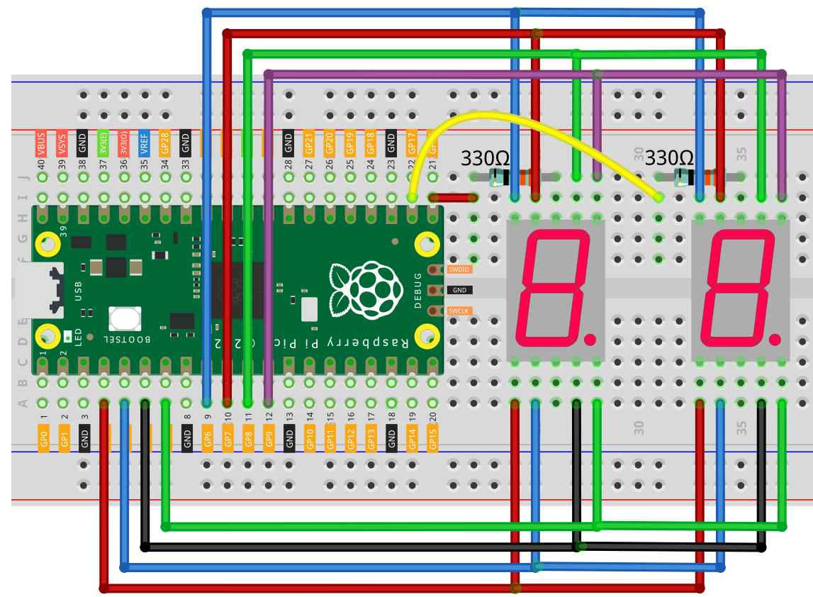
Example 2 - Fritzing Diagram
Code
from machine import Pin
import utime

# Define the GPIO pins for each segment
segments = (8,9,4,3,2,7,6,5)

# Define the digit patterns for 0-9 on the 7-segment display
# 0 means the segment is on, 1 means the segment is off
patterns = [
    (0, 0, 0, 0, 0, 0, 1, 1),  # 0
    (1, 0, 0, 1, 1, 1, 1, 1),  # 1
    (0, 0, 1, 0, 0, 1, 0, 1),  # 2
    (0, 0, 0, 0, 1, 1, 0, 1),  # 3
    (1, 0, 0, 1, 1, 0, 0, 1),  # 4
    (0, 1, 0, 0, 1, 0, 0, 1),  # 5
    (0, 1, 0, 0, 0, 0, 0, 1),  # 6
    (0, 0, 0, 1, 1, 1, 1, 1),  # 7
    (0, 0, 0, 0, 0, 0, 0, 1),  # 8
    (0, 0, 0, 1, 1, 0, 0, 1)   # 9
]

# Initialize the GPIO pins
pins = [Pin(seg, Pin.OUT) for seg in segments]

# Initialize the common cathodes for the displays
displays = [Pin(16, Pin.OUT, value=1), Pin(17, Pin.OUT, value=1)]

def display_digit(display, digit):
    # Turn off both displays
    displays[0].value(1)
    displays[1].value(1)

    # Get the pattern for the digit
    pattern = patterns[digit]

    # Set each segment to the correct state
    for i in range(8):
        pins[i].value(pattern[i])

    # Turn on the correct display
    displays[display].value(0)

    # Wait a short time
    utime.sleep_ms(12)

    # Turn off the display
    displays[display].value(1)

# Test the displays
# Test the displays
while True:
    for i in range(10):
        for j in range(10):
            start = utime.ticks_ms()
            while utime.ticks_diff(utime.ticks_ms(), start) < 1000:
                display_digit(0, i)
                display_digit(1, j)
Code explanation
from machine import Pin
import utime

# Define the GPIO pins for each segment
segments = (8,9,4,3,2,7,6,5)

# Define the digit patterns for 0-9 on the 7-segment display
# 0 means the segment is on, 1 means the segment is off
patterns = [
    (0, 0, 0, 0, 0, 0, 1, 1),  # 0
    (1, 0, 0, 1, 1, 1, 1, 1),  # 1
    (0, 0, 1, 0, 0, 1, 0, 1),  # 2
    (0, 0, 0, 0, 1, 1, 0, 1),  # 3
    (1, 0, 0, 1, 1, 0, 0, 1),  # 4
    (0, 1, 0, 0, 1, 0, 0, 1),  # 5
    (0, 1, 0, 0, 0, 0, 0, 1),  # 6
    (0, 0, 0, 1, 1, 1, 1, 1),  # 7
    (0, 0, 0, 0, 0, 0, 0, 1),  # 8
    (0, 0, 0, 1, 1, 0, 0, 1)   # 9
]
In this section, we import the necessary modules (machine and utime), and then define the GPIO pins used for each segment of the 7-segment display. The segments tuple contains the pin numbers. We also define patterns, a list of tuples that represents the digit patterns for the numbers 0 to 9. In each tuple, a 0 represents an illuminated segment, and a 1 represents a segment that is turned off.
# Initialize the GPIO pins
pins = [Pin(seg, Pin.OUT) for seg in segments]

# Initialize the common cathodes for the displays
displays = [Pin(16, Pin.OUT, value=1), Pin(17, Pin.OUT, value=1)]
Initialize the GPIO pins for each segment using the Pin class. List comprehension is used to create a list of Pin objects. Initialize the common cathode pins for the displays. The Pin function is used to set up Pin objects for GPIO pins 16 and 17, with an initial value of 1 to turn off the displays.
def display_digit(display, digit):
    displays[0].value(1)  # Turn off display 0
    displays[1].value(1)  # Turn off display 1

    pattern = patterns[digit]  # Get the pattern for the given digit

    # Set each segment to the correct state
    for i in range(8):
        pins[i].value(pattern[i])

    displays[display].value(0)  # Turn on the specified display

    utime.sleep_ms(12)  # Wait for a short time

    displays[display].value(1)  # Turn off the specified display
Define a function display_digit that takes a display and digit as arguments. This function displays a specific digit on a specific display. It turns off both displays, sets the segment pins based on the digit’s pattern, turns on the appropriate display, waits for a short time, and turns off the display.
while True:
    for i in range(10):
        for j in range(10):
            start = utime.ticks_ms()
            while utime.ticks_diff(utime.ticks_ms(), start) < 1000:
                display_digit(0, i)  # Display digit i on display 0
                display_digit(1, j)  # Display digit j on display 1
This code repeatedly displays two digits on a 7-segment display with multiplexing through GPIO pins GP15 (display 0) and GP17 (display 1).