8 LED Projects
From blinking a single LED to building a binary clock, in this tutorial I will show you from the total beginner project to more advance.
Introduction
LEDs are often the very first component people use when learning electronics.
They are cheap, simple, and instantly show whether your code is working.
What many beginners do not realize is that LEDs scale extremely well.
In this tutorial, we will walk through eight LED-based projects using the Raspberry Pi Pico, starting from the absolute basics and gradually building toward more advanced ideas.
The hardware barely changes, what changes is the logic, structure, and way we think about the problem.
This makes LEDs one of the best teaching tools in embedded systems.
Why Learn with LEDs?
LEDs provide immediate visual feedback.
There is no ambiguity, the system either behaves as expected or it does not.
Using LEDs allows you to focus on:
- GPIO control
- Timing and delays
- State machines
- PWM and brightness control
- Arrays and loops
- Representing information visually
By the end of these projects, you are no longer “just turning on lights”.
Hardware Used
All projects in this guide use the same basic setup:
- Raspberry Pi Pico or Pico W
- LEDs (single LEDs and RGB / WS2812B)
- Resistors (220–330 Ω)
- Breadboard
- Jumper wires
- USB cable
- Computer with MicroPython
As the projects progress, the code becomes more complex
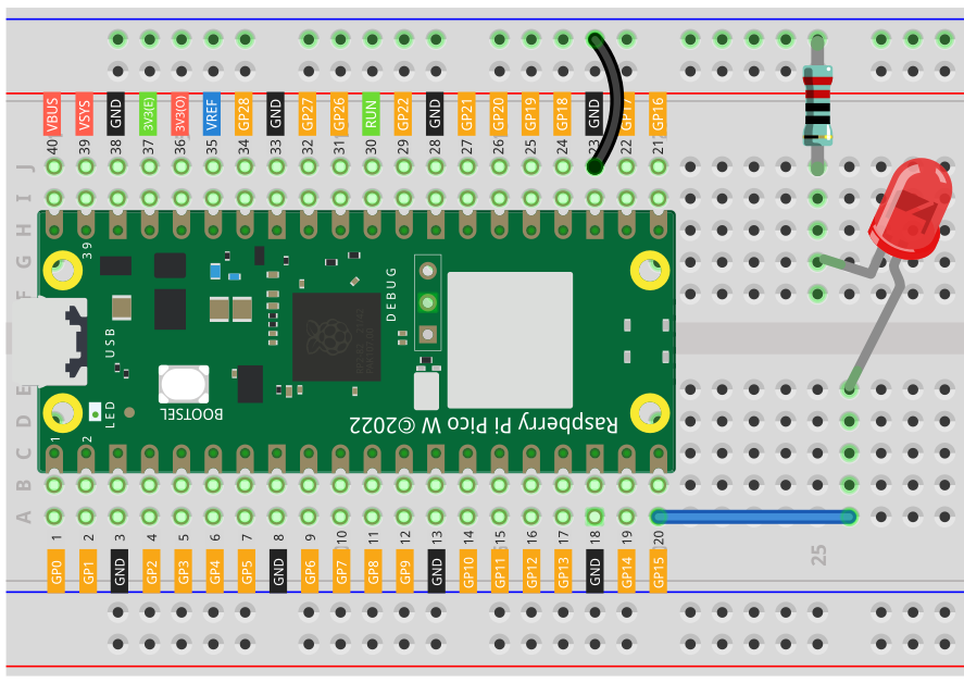
Level 1 — Blinking an LED
The first project is the classic LED blink.
This project teaches:
- How to connect an LED correctly
- How to use a GPIO pin as an output
- How to upload and run MicroPython code
- How timing delays work
Although simple, this step verifies that your wiring, firmware, and development environment all work correctly.
This single LED blinking is the foundation for everything that follows.
Connection Diagram
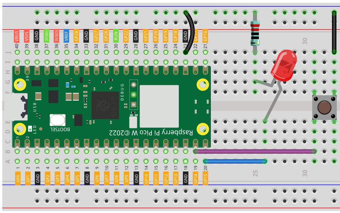
Level 2 — Button Controlled LED
In level two, we introduce input.
Instead of the Pico controlling the LED on its own, it now reacts to a button press.
This project teaches:
- Reading digital inputs
- Pull-up resistors
- Event-driven thinking
This is the moment where a project stops being passive and becomes interactive.
Connection Diagram
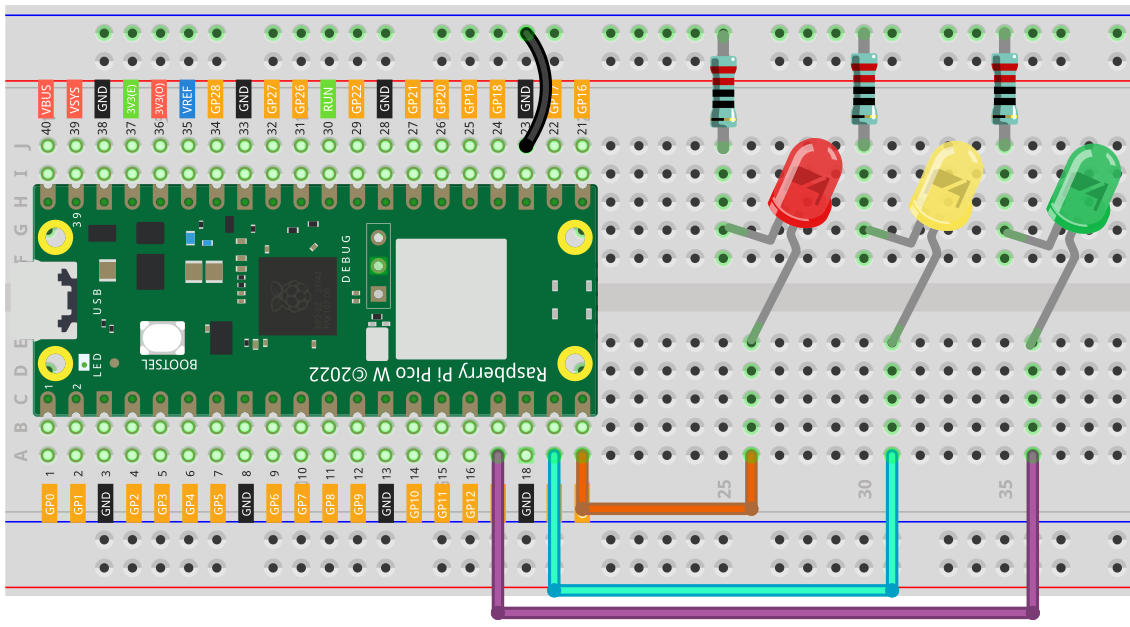
Level 3 — Traffic Light System
The traffic light project introduces structured timing and logic.
Multiple LEDs are used together, each representing a different state:
- Red
- Yellow
- Green
This project teaches:
- Sequential logic
- Timing control
- State-based behavior
Even though it looks simple, this is your first real system.
Connection Diagram
Level 4 — PWM LED Fading
At level four, we move beyond simple on/off control.
Using PWM (Pulse Width Modulation), the LED smoothly fades in and out.
This project teaches:
- PWM concepts
- Simulating analog behavior with digital pins
- Brightness control
PWM is a fundamental concept used far beyond LEDs, including motor control and power regulation.
Connection Diagram
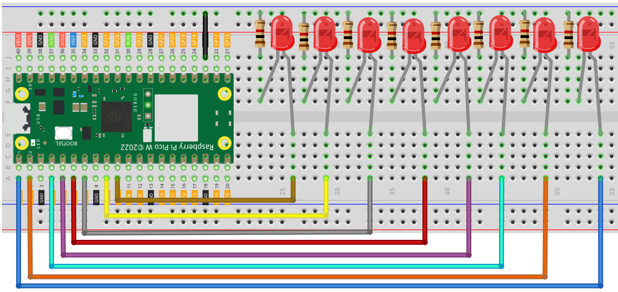
Level 5 — LED Bar Graph
In this project, multiple LEDs work together to represent information.
The LEDs may represent:
- Progress
- Battery level
- Sensor output
This project teaches:
- Arrays and loops
- Mapping values to outputs
- Thinking in terms of groups rather than individual pins
At this point, code structure becomes more important than wiring.
Connection Diagram
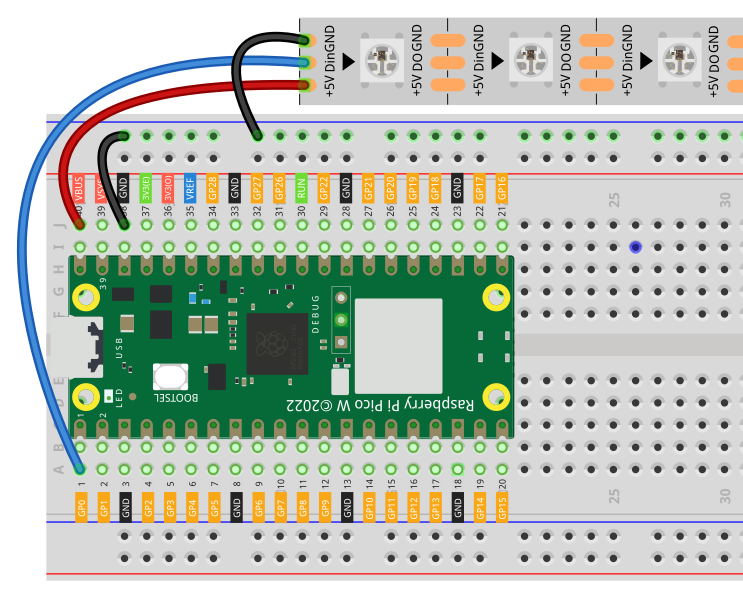
Level 6 — Addressable RGB LEDs (NeoPixels)
Addressable LEDs drastically increase what is possible.
Each LED can have:
- Its own color
- Its own brightness
- Its own position in an animation
This project teaches:
- Working with LED libraries
- Animation logic
- Color representation
This is often the point where projects become visually exciting and highly motivating.
Connection Diagram
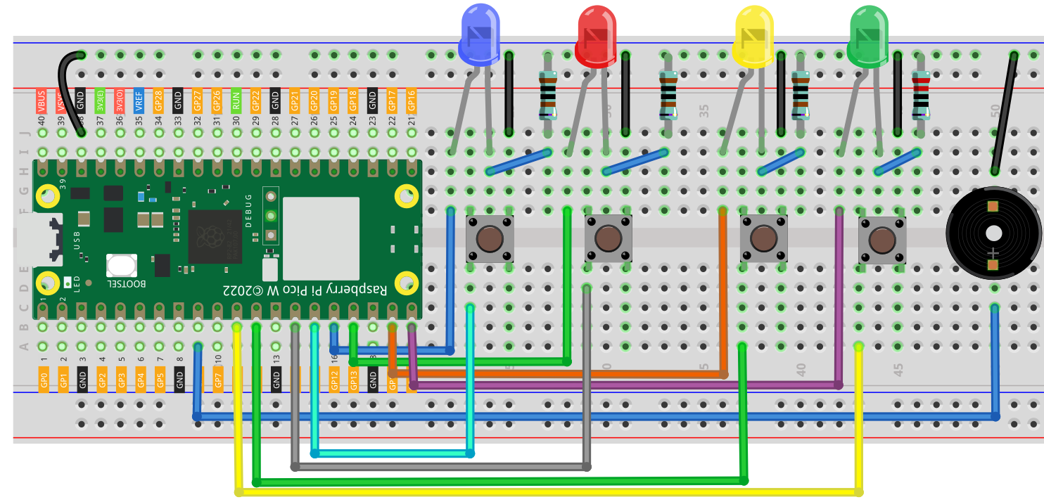
Level 7 — Simon Says Game
Level seven combines everything learned so far into a complete interactive game.
The Pico:
- Generates random sequences
- Displays them using LEDs
- Reads user input via buttons
- Checks correctness
This project teaches:
- Game logic
- Randomness
- State machines
- Debugging complex behavior
Mistakes are expected — and valuable.
Connection Diagram
Level 8 — Binary Clock
The final project in this guide is a binary clock.
Instead of displaying numbers directly, time is represented using LEDs in binary form.
This project teaches:
- Binary representation
- Mapping abstract concepts to LEDs
- Timekeeping logic
At this stage, LEDs are no longer “lights” — they are symbols carrying information.
Connection Diagram
What Changed from Level 1 to Level 8?
Interestingly, very little hardware changed.
What evolved was:
- The complexity of the code
- The way problems were broken down
- The mental model of how systems behave
This is why LEDs are such a powerful learning tool.
Where to Go Next
Once you are comfortable with these projects, you can extend them further:
- Add sound-reactive LEDs
- Build distance-based LED displays
- Create menu systems
- Combine LEDs with keypads or sensors
- Design custom PCBs
Final Thoughts
LEDs are often dismissed as beginner components, but they are capable of teaching nearly every core concept in embedded systems.
If you can control LEDs confidently, you can control almost anything.
Related Projects
- LED Binary Clock (Full Build)
- Simon Says Game with Pico
- RGB LED Animations
- Input Handling with Buttons