Pico Alarm Clock
Introduction
Welcome to this tutorial on creating an alarm clock with the Raspberry Pi Pico W.
Component List
Here is the breakdown of components needed for the Pico W Alarm Clock (assuming you have basic tools):
| Components | Quantity |
|---|---|
| Custom PCB | 1 |
| Raspberry Pi Pico W | 1 |
| 2.54 20 pin Header | 2 |
| Buzzer | 1 |
| 2n2222 npn | 1 |
| 1K Ohm Resistor | 1 |
Schematic Diagram
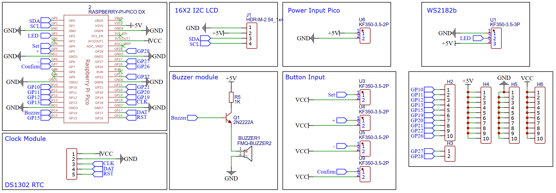
The schematic diagram was created using EasyEDA. All components used are through-hole types, making the soldering process easier and more accessible.
PCB Design
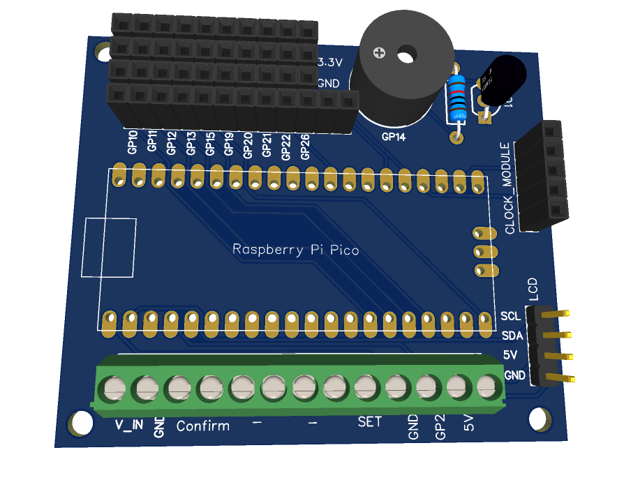
The PCB size was minimized to optimize space and ensure efficient use of the available area.
Order PCB (JLCPCB)
The PCB was ordered through JLCPCB. They offer great PCBs at a low cost and have promotions and coupons available throughout the year. You can sign up using here, or using the following link:
https://jlcpcb.com/?from=Nerd that will support me as a creator to keep making content that is accessible and open source at no charge to you.
Ordering the PCB is very simple:
Download the Gerber file here.
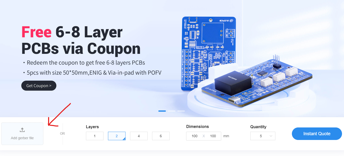
Click on Add Gerber file
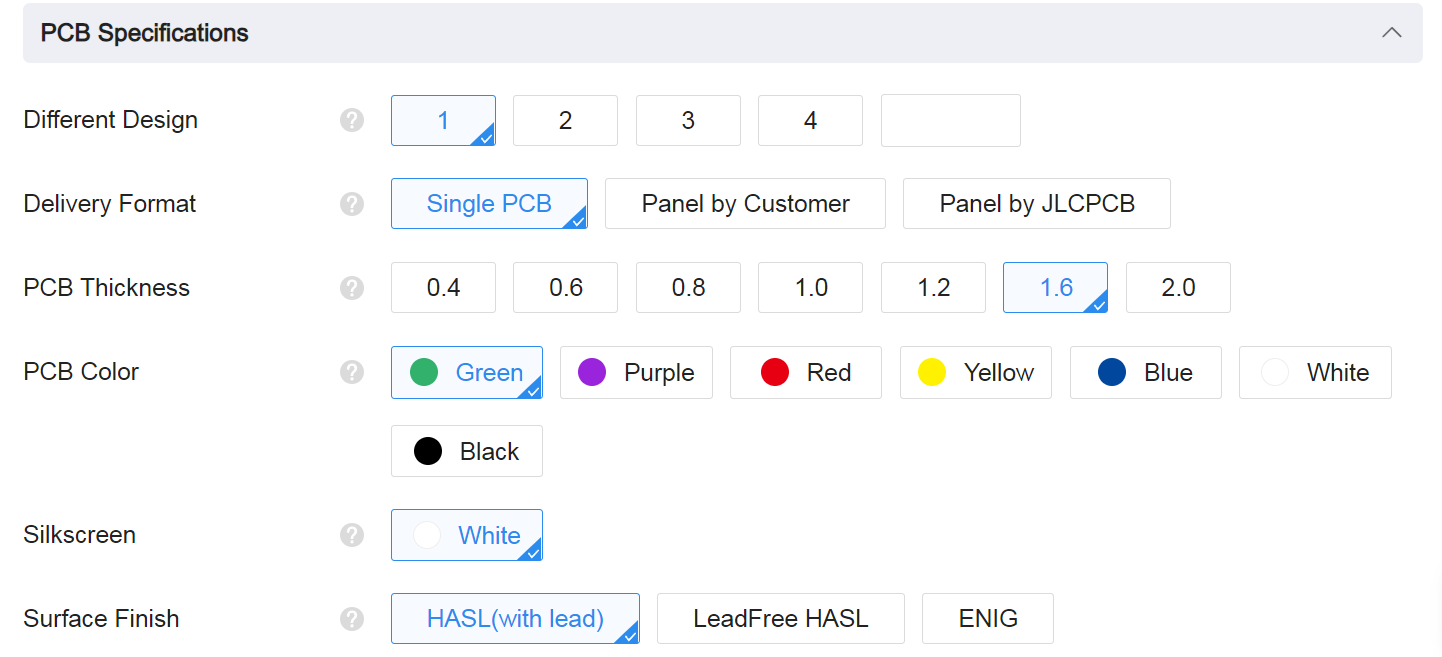
leave all the settings as default given. You might want change the PCB color which you can do here:
Enter you shipping details, save to cart
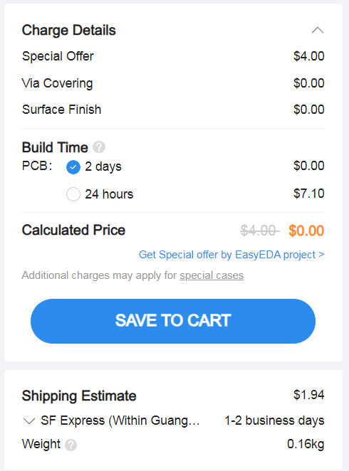
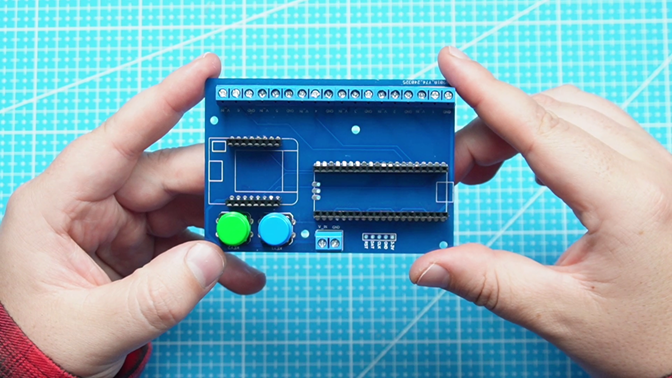
Then after a few days depending on your location you will receive your great quality PCB.
Code
In order to use the Fibonnaci Clock, you will have to create an account on IP Geolocation in order to access the API to get the correct time over Wifi. Visit the following tutorial to learn about it: Before we dive into the code, you’ll need to set up an API key with the IP Geolocation API. Follow these steps to get your key: Tutorial
Download the full demo code here, which include the neopixel and urequest library.
Enclosure Design
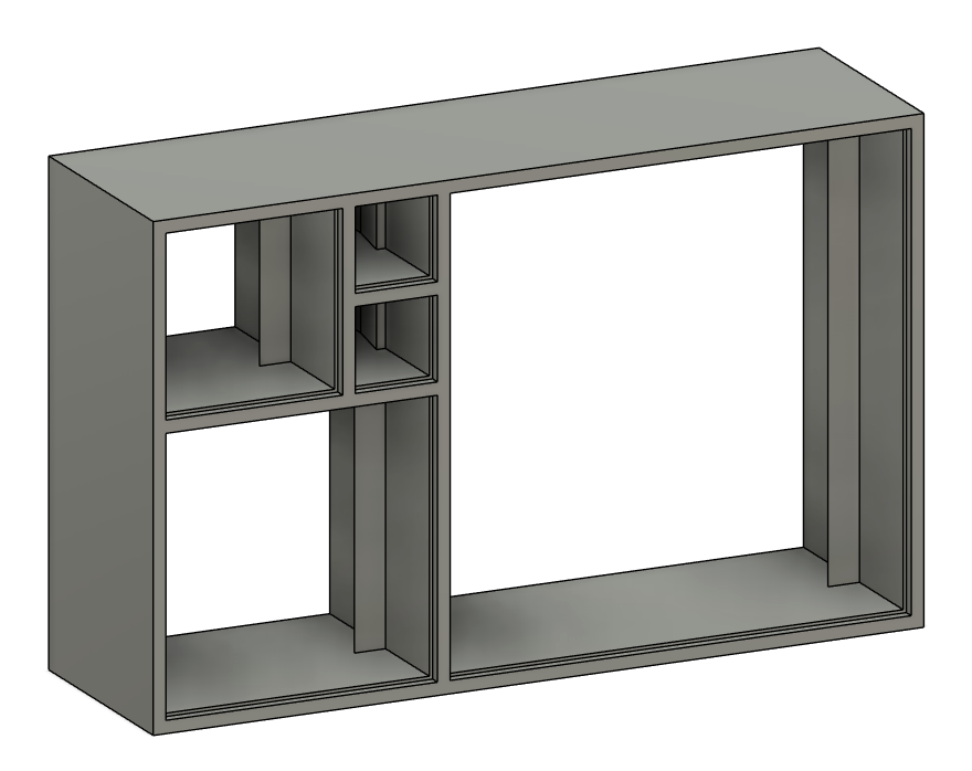
The enclosure was designed in Fusion360. The enclosure consist of three main parts. The main body which the LED bracket will be inserted which you need to solder all the LED rows and then the insert squares which will diffuse the light from the LEDs. The STL files are available here
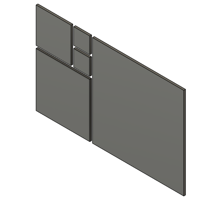
The parts does not require any supports when printing.
If anyone decides to recreate this project and comes up with an improved design for the case, please feel free to share it with me. I would love to see what you create!
Conclusion
The enclosure still needs to be updated as it does not have a back cover yet lol. So future plans is to make a version which will look more like golden ratio, and use LEDs connected on PCB.