Fibonacci Clock Version 2
YouTube Video
Introduction
In this tutorial, we build a Fibonacci Clock using the Raspberry Pi Pico W, a custom PCB, and WS2812B addressable LEDs.
Instead of displaying time using traditional numbers or clock hands, this clock represents time using colored Fibonacci blocks. Each block corresponds to a number in the Fibonacci sequence and lights up in different colors to show hours and minutes.
The Fibonacci sequence is a series of numbers where each number is the sum of the two previous ones. The first five numbers are:
1, 1, 2, 3, and 5
Using these five values, we can represent any hour (1–12) and minute value in 5‑minute increments. Each block contains a group of LEDs mounted on a custom PCB, and a 3D‑printed enclosure makes the Fibonacci squares clearly visible.
The Raspberry Pi Pico W connects to Wi‑Fi, synchronizes the current time using an online API, calculates the Fibonacci representation of the time, and lights the blocks accordingly using MicroPython.
This project combines math, electronics, programming, and design into a functional and educational clock.
How to Read the Fibonacci Clock
At first glance, a Fibonacci Clock may look confusing, but it follows a simple set of rules.
1. Fibonacci Blocks
The clock is made up of five blocks, each representing a Fibonacci number:
numbers.png)
Each block may be lit in a different color depending on how it contributes to the time.
2. Color Meanings
Each block uses color to indicate its purpose:
- Red → Hours
- Blue → Minutes
- Green → Both hours and minutes
- White → Not used
3. Reading the Hours
To calculate the hour:
- Add the values of all red blocks.
- Add the values of all green blocks.
Hour = Red blocks + Green blocks
4. Reading the Minutes
To calculate the minutes:
- Add the values of all blue blocks.
- Add the values of all green blocks.
- Multiply the total by 5.
Minutes = (Blue blocks + Green blocks) × 5
5. Full Time Example
Demo 1
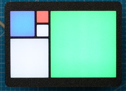
- Red block: 1
- Blue block: 2
- Green block: 5
Hour = Red blocks + Green blocks
Minutes = (Blue blocks + Green blocks) × 5
Then:
- Hours = 1 + 5 = 6
- Minutes = (2 + 5) × 5 = 35
➡️ The time is 6:35
Demo 2
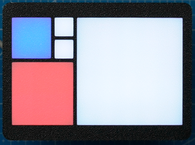
- Red block: 3
- Blue block: 2
- Green block: 0
Hour = Red blocks + Green blocks
Minutes = (Blue blocks + Green blocks) × 5
Then:
- Hours = 3 = 3
- Minutes = (2) × 5 = 10
➡️ The time is 3:10
Demo 3
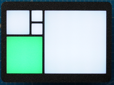
If the clock shows:
- Red block: 0
- Blue block: 0
- Green block: 3
Hour = Red blocks + Green blocks Minutes = (Blue blocks + Green blocks) × 5
Then:
- Hours = 3 = 5
- Minutes = (3) × 5 = 15
➡️ The time is 3:15
Why This Works
Because Fibonacci numbers can be combined in many ways, these five blocks are sufficient to represent all hours from 1 to 12 and all minute values from 0 to 55 (in 5‑minute steps).
The Fibonacci Clock is a unique way to visualize time while demonstrating concepts from mathematics, logic, and microcontrollers.
Component List
Here is the breakdown of components needed for the Fibonnaci Clock:
| Components | Quantity |
|---|---|
| Custom PCB | 1 |
| Raspberry Pi Pico W | 1 |
| WS2810B LEDs | 50 |
| 2.54 20 pin Header | 2 |
| M3 Socket Head 0 35mm | 2 |
| USB C socket | 1 |
The following tools will be needed:
| Equipment |
|---|
| Multicolor - 3D Printer |
| Soldering Hot plate |
| Allen Wrench |
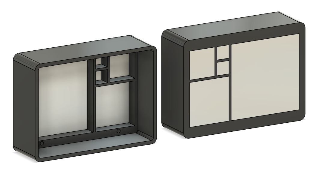
Enclosure Design
I designed the enclosure for the clock first. While this might sound unusual to do before designing the PCB, the reason is straightforward: by designing the enclosure first, I could define the five blocks that represent the Fibonacci sequence, then export the front face as a DXF file.
This DXF was later used as a reference when designing the PCB, ensuring that the LEDs are positioned correctly behind each block.
The enclosure was designed using Fusion 360.
The enclosure consists of two parts.
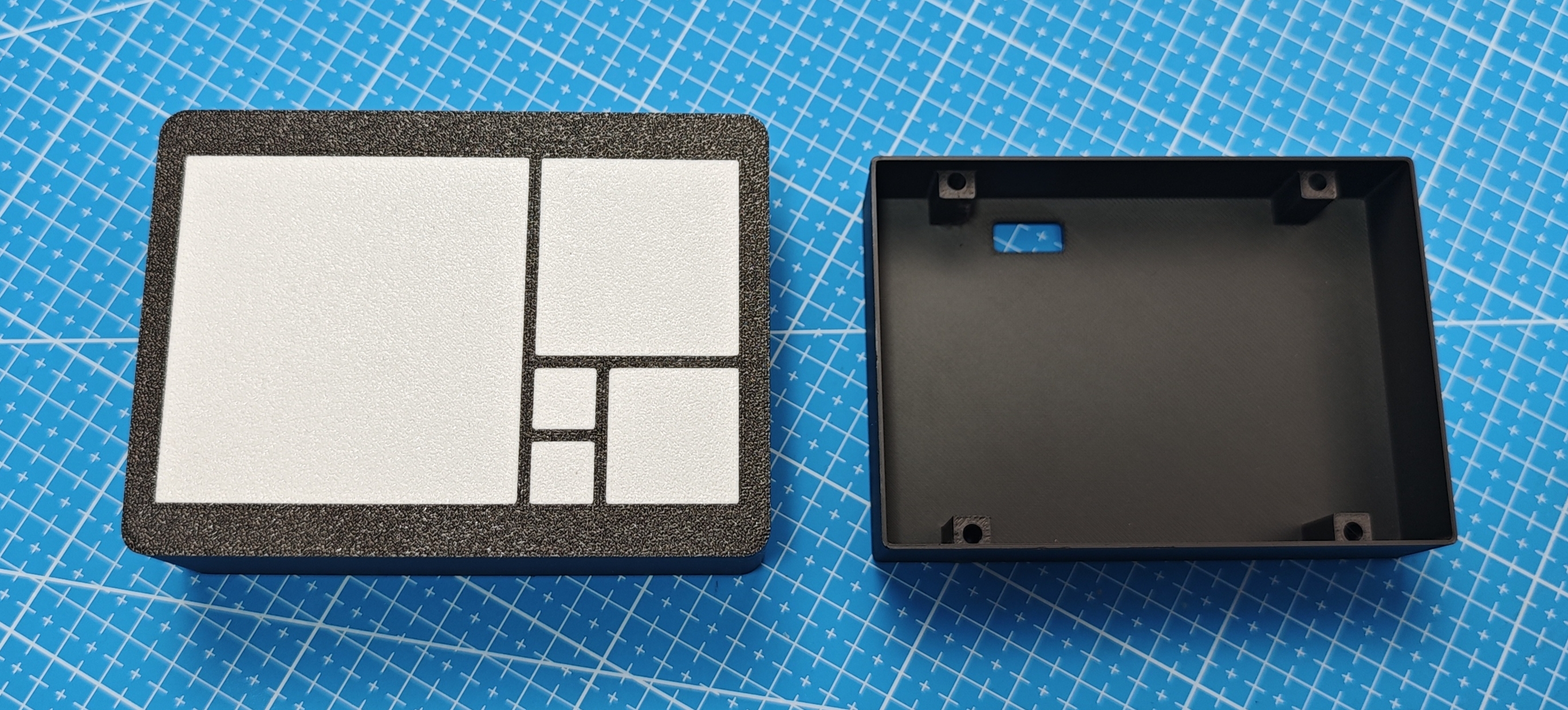
Main Body
The first part is the main body, which contains the five blocks used to display the time. These blocks were printed using white filament with a 0.4 mm layer height, allowing the LEDs to diffuse the light evenly.
One of the main challenges during this stage was determining how far the LEDs should be positioned from the blocks to achieve good light diffusion without visible hotspots.
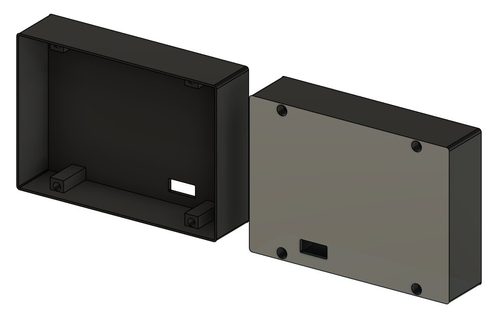
Back Cover
The second part is the back cover, which slots into the main enclosure and is held in place using M3 hex screws. This section also houses the electronics.
The clock is powered via USB-C, making it easy to power from a wall adapter or power bank.
PCB Design (EasyEDA)
For the final version of this Fibonacci Clock, I designed a custom PCB to keep the wiring clean, compact, and reliable. The PCB was designed using EasyEDA, which integrates well with JLCPCB and makes the ordering process straightforward.
Why a Custom PCB?
While the prototype used an LED strip and wiring, a custom PCB offers several advantages:
- Cleaner and more reliable connections
- Consistent LED spacing and layout
- Smaller overall footprint
- Lower assembly time
- Reduced cost when ordering multiple boards
To keep manufacturing costs low, the board size was intentionally kept under 10 × 10 cm.
LED Layout
The clock uses 50 WS2812B LEDs, arranged to represent the Fibonacci sequence:
- 1
- 1
- 2
- 3
- 5
Each LED corresponds to a block of the clock. In the final version, these LEDs light up different colors to represent hours and minutes.
All LEDs are connected in series, meaning:
- DIN → DOUT from one LED to the next
- A single data line from the Raspberry Pi Pico W controls all LEDs
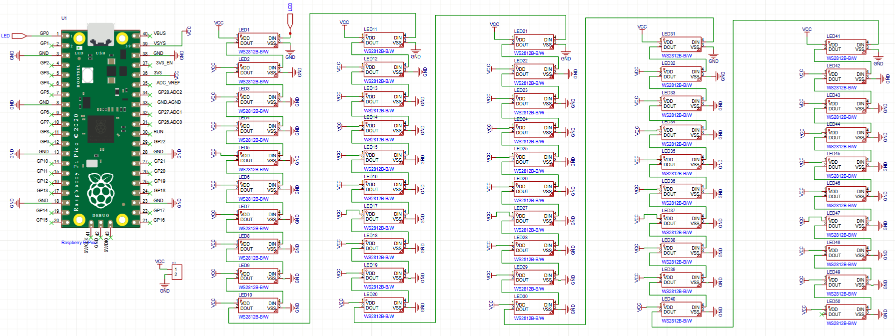
Schematic Design
In EasyEDA, I first created the schematic:
- Raspberry Pi Pico W connected to:
- WS2812B data line
- 5V power rail
- Common ground
Once the schematic was complete, I converted it to a PCB layout.
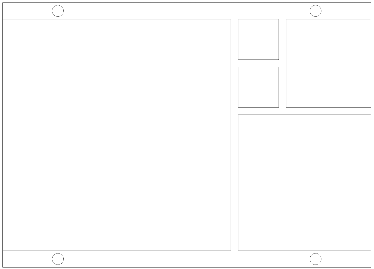
PCB Layout
When routing the board, I focused on:
- Keeping data lines as short as possible
- Using wide traces for 5V and GND
- Placing LEDs in positions that align with the clock face
- Adding mounting holes for the 3D-printed enclosure
Silkscreen labels were added to make assembly and debugging easier.
Final Checks
Before exporting the Gerber files, I:
- Ran EasyEDA’s Design Rule Check (DRC)
- Verified LED orientation
- Double-checked power and ground connections
Once everything checked out, the Gerber files were exported and prepared for manufacturing.
Ordering the Custom PCB (JLCPCB)
Once the PCB design was finalized in EasyEDA, the next step was to have the board manufactured. I chose JLCPCB because of their low cost, good quality, and seamless integration with EasyEDA.
Exporting the Gerber Files
From EasyEDA, I exported the Gerber files, which contain all the information needed to manufacture the PCB. EasyEDA can export these files directly in a format compatible with JLCPCB.
Before uploading the files, I double-checked:
- Board dimensions (under 10 × 10 cm)
- LED orientation
- Power and ground connections
- Mounting hole placement
You can download the PCB Gerber file here: Link
Uploading to JLCPCB
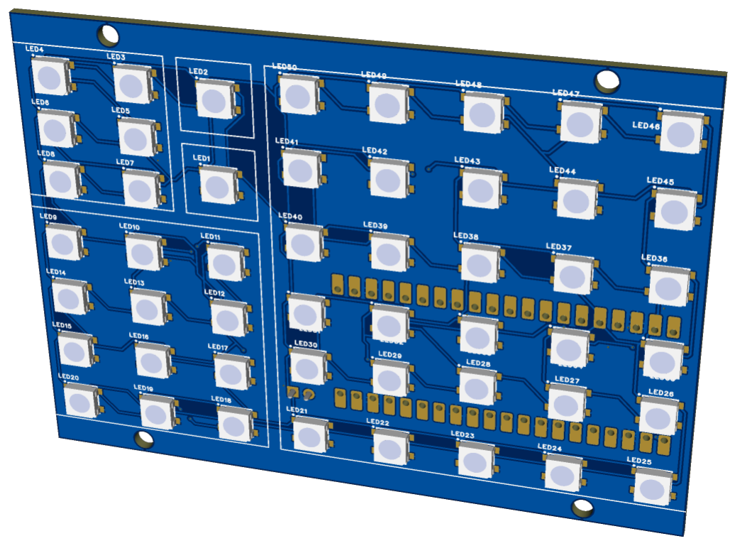
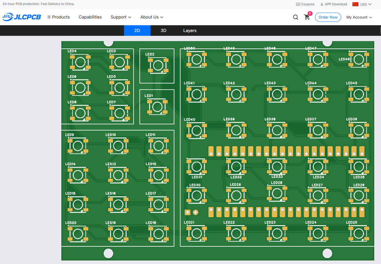
After exporting the Gerber files, I uploaded them to the JLCPCB website. The board preview tool was used to visually confirm that everything looked correct.
PCB Specifications
For this project, I used the following settings:
- PCB Layers: 2
- PCB Thickness: 1.6 mm
- Copper Weight: 1 oz
- Surface Finish: HASL (Lead-Free)
- Solder Mask Color: Your choice
Ordering and Delivery
Once the settings were confirmed, I placed the order. Manufacturing usually takes only a few days, and shipping time depends on the selected delivery option.
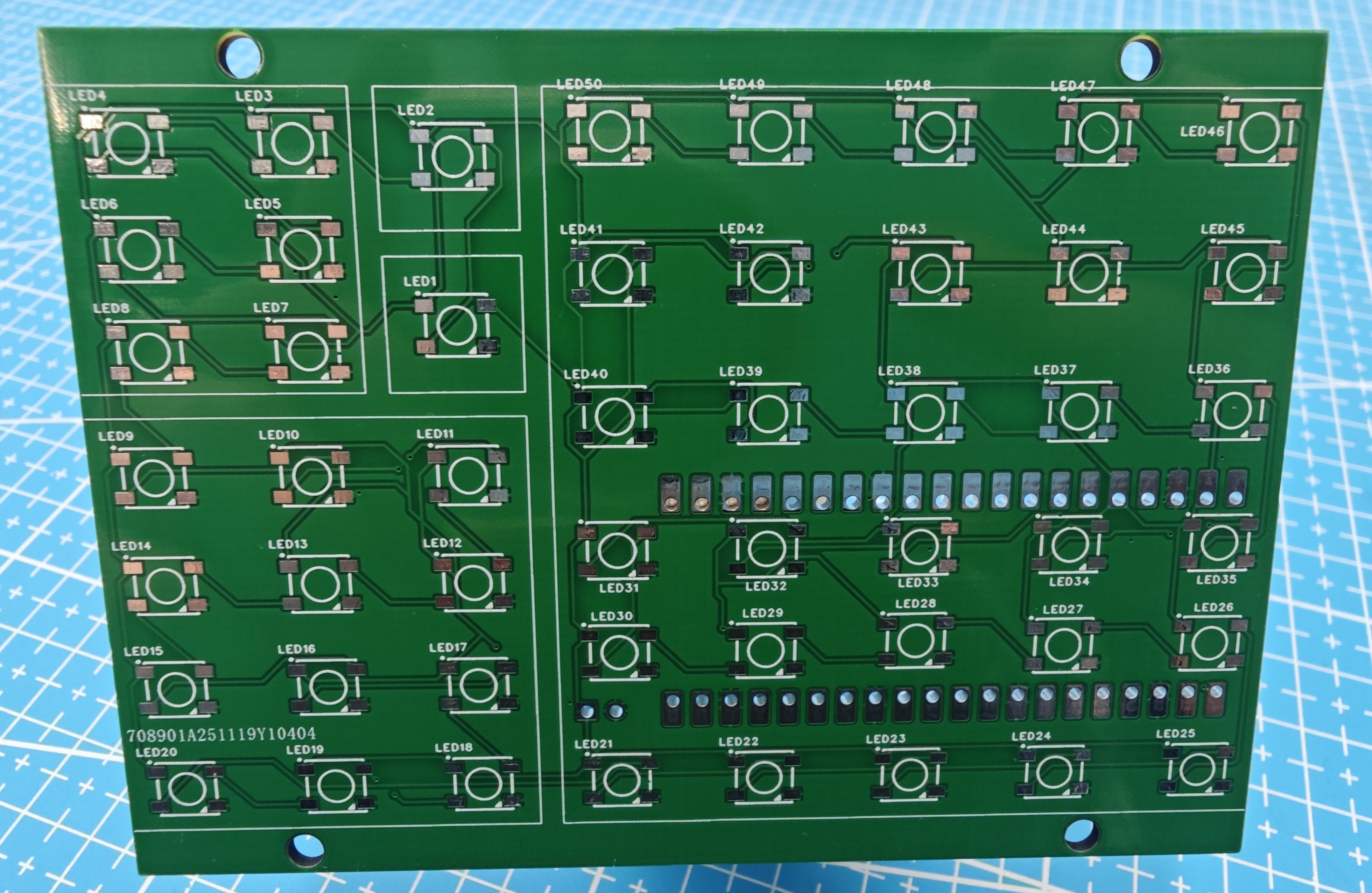
When the PCBs arrived, I inspected them for:
- Correct dimensions
- Clean solder mask
- Properly drilled holes
- Accurate silkscreen
Everything looked good and was ready for assembly.
Hot Plate Soldering the LEDs
To solder the WS2812B LEDs onto the PCB, I used a hot plate instead of a traditional soldering iron. This method is especially useful for surface-mount components, as it allows all pads to be soldered evenly at the same time.
What You’ll Need
- Custom PCB
- WS2812B LEDs
- Solder paste
- Tweezers
- Hot plate (reflow hot plate)
Applying the Solder Paste
Apply a small amount of solder paste to each LED pad. Avoid using too much paste, as this can cause solder bridges.
Placing the LEDs
Using tweezers, carefully place each LED onto its footprint, ensuring correct orientation. WS2812B LEDs are polarity-sensitive, so double-check the DIN direction and silkscreen markings.
Reflowing on the Hot Plate
Place the PCB on the hot plate and slowly increase the temperature. As the solder paste melts, the LEDs will self-align into position.
Once all solder joints look shiny and fully reflowed, turn off the heat and allow the PCB to cool naturally. Do not move the board while the solder is molten.
Inspection and Cleanup
After cooling:
- Check for solder bridges
- Ensure all pads are soldered
- Confirm LEDs are flat on the PCB
Soldering the Pico Headers and Power Connections
Solder the header pins onto the Raspberry Pi Pico. Once complete, snap the USB-C adapter into the 3D-printed enclosure.
After it is securely in place, solder the 5V and GND wires from the USB-C adapter to the corresponding holess on the PCB.
Programming the Pico W and Connecting It to the PCB
At this stage, the Pico W can be connected to the PCB and powered through the USB port before assembling the enclosure. This allows the code to be uploaded, tested, and debugged while everything remains easily accessible.
All the code for the project can be downloaded here.
LED Test Code
This simple script below is used to test all the 50 LEDs soldered to the PCB. Make sure to upload the neopixel library to the Pico first before running the script.
from neopixel import Neopixel
import utime

# ============================
# LED STRIP SETUP
# ============================
NUM_LEDS = 50
PIN_NUM = 0
STATE_MACHINE = 0

np = Neopixel(NUM_LEDS, STATE_MACHINE, PIN_NUM, "GRB")

# IMPORTANT: start low to avoid brownout
np.brightness(100)  # 1–255

# ============================
# COLOR DEFINITIONS
# ============================
WHITE = (255, 255, 255)
RED   = (255, 0, 0)
GREEN = (0, 255, 0)
BLUE  = (0, 0, 255)

# ============================
# TURN ON ALL LEDs
# ============================
for i in range(NUM_LEDS):
    np.set_pixel(i, WHITE)

np.show()

print("All 50 LEDs ON")

# Keep running so LEDs stay lit
while True:
    utime.sleep(1)
Configuration File (config.json)
The config.json file stores all user-specific settings separately from the main program. This makes it easy to update Wi-Fi credentials, time zones, or API keys without modifying the main code.
Setting Up the Time API (ipgeolocation.io)
To automatically set the correct time, this project uses the ipgeolocation.io Time Zone API.
1️⃣ Create a Free Account
- Go to the ipgeolocation.io website
- Create a free account
- Generate an API key
The free tier is sufficient since the time is only fetched at startup.
2️⃣ Add the API Key to config.json
"date_time_api": "YOUR_API_KEY_HERE",
"time_zone": "Asia/Shanghai"
Replace the time zone with your local region if needed.
3️⃣ How the Code Uses the API
On startup, the Pico W:
- Connects to Wi-Fi
- Sends a request to the ipgeolocation API
- Receives the current date and time
- Updates the internal RTC
If the time sync is successful, the LEDs briefly turn green.
If Wi-Fi fails, the LEDs turn yellow, and the clock continues running using the last known time.
4️⃣ Why an Online Time API Is Used
The Raspberry Pi Pico W does not have a battery-backed RTC. Using an online time API ensures:
- Accurate time after power loss
- No manual time setting required
- Correct handling of time zones
Understanding the Main Code
1️⃣ Boot Delay
utime.sleep(5)
A short delay ensures reliable startup when powered from an external USB supply.
2️⃣ LED Setup and Fibonacci Blocks
NUM_LEDS = 50
BLOCKS = [1, 1, 6, 12, 30]
The LEDs are divided into five Fibonacci-based blocks to create a balanced visual layout.
3️⃣ Color Definitions
- Red → Hours
- Blue → Minutes
- Green → Hours + Minutes
- White → Inactive blocks
The first two LEDs are intentionally brighter to balance illumination.
4️⃣ Wi-Fi and Time Synchronization
Startup indicators:
- Purple → Boot
- Cyan → Wi-Fi connected
- Lime → Time synced
- Yellow → Error
5️⃣ Fibonacci Time Calculation
Hours and minutes are converted into Fibonacci values, with minutes rounded to the nearest 5.
6️⃣ Main Loop
The loop:
- Reads time from the RTC
- Calculates the Fibonacci state
- Updates the LED blocks
- Refreshes every second
Final Assembly
With the PCB fully assembled and the code tested, the final step is to install everything into the enclosure.
Installing the PCB
- Align the LEDs behind the Fibonacci blocks
- Ensure the USB-C connector is accessible
Closing the Enclosure
- Slide the back cover into place
- Secure it using M3 hex screws
Conclusion
This Fibonacci Clock Version 2 brings together mathematics, electronics, and design into a practical and visually interesting project. By combining the Raspberry Pi Pico W, a custom PCB, and WS2812B addressable LEDs, the clock transforms an abstract mathematical concept into something you can see, build, and interact with every day.
Designing the enclosure first helped ensure clean light diffusion and accurate LED placement, while the custom PCB kept the wiring compact and reliable. Using Wi-Fi time synchronization removes the need for manual time setting and makes the clock far more practical for daily use.
Beyond being a functional desk clock, this project works especially well as a learning tool. It demonstrates how Fibonacci numbers can be applied in real-world designs, while also introducing concepts such as addressable LEDs, PCB design, 3D printing, and MicroPython programming.
This build is easy to customize—whether that’s changing colors, adjusting brightness, modifying the enclosure, or extending the code with additional features like animations or alternative time displays. If you’re interested in combining math with hands-on electronics, the Fibonacci Clock is a rewarding project that looks great and sparks conversation.
Happy building—and as always, keep things nerdy