Multiple Button Input from ADC
YouTube Video
Introduction
Normally, each push button uses its own GPIO pin. That is simple, but it does not scale well if you want a keypad, a menu controller, or several input buttons on a small board.
One useful trick is to connect multiple buttons to a single ADC pin using different or same resistor values. Each button creates a different voltage, and the Pico reads that voltage with the ADC. Your code then checks the measured value and decides which button was pressed.
This is a common technique in small embedded systems because it reduces pin usage while still allowing multiple inputs.
What This Tutorial Teaches
In this tutorial, you will learn:
- how the Pico ADC works
- how resistor ladders create different voltage levels
- how to wire multiple buttons to one analog input
- how to detect button presses by checking ADC ranges
Why Use ADC for Multiple Buttons?
Advantages:
- saves GPIO pins
- useful for menu navigation
- helpful in handheld projects and small control panels
- works well when only one button is pressed at a time
Tradeoffs:
- not ideal for detecting several buttons at the same time
- requires threshold tuning
- resistor tolerances can slightly change the measured values
How It Works
Each button connects the ADC pin through a different resistor path. When a button is pressed, the ADC sees a different voltage.
For example:
- no button pressed -> ADC reads near full scale or near zero depending on the circuit
- button 1 pressed -> ADC reads one voltage
- button 2 pressed -> ADC reads a different voltage
- button 3 pressed -> ADC reads another voltage
Your code does not check for exact values. Instead, it checks if the ADC reading falls inside a range.
Components Needed
| Component | Quantity |
|---|---|
| Raspberry Pi Pico or Pico W | 1 |
| Breadboard | 1 |
| Push buttons | 3 to 5 |
| Resistors | Several |
| Jumper wires | Several |
| USB cable | 1 |
Suggested Resistor Values
In this example only 1k Ohm resistors has been used but you can build the button ladder with many resistor combinations. A simple starting set is:
1k2.2k4.7k10k
The exact values are less important than making sure the resulting ADC readings are clearly separated.
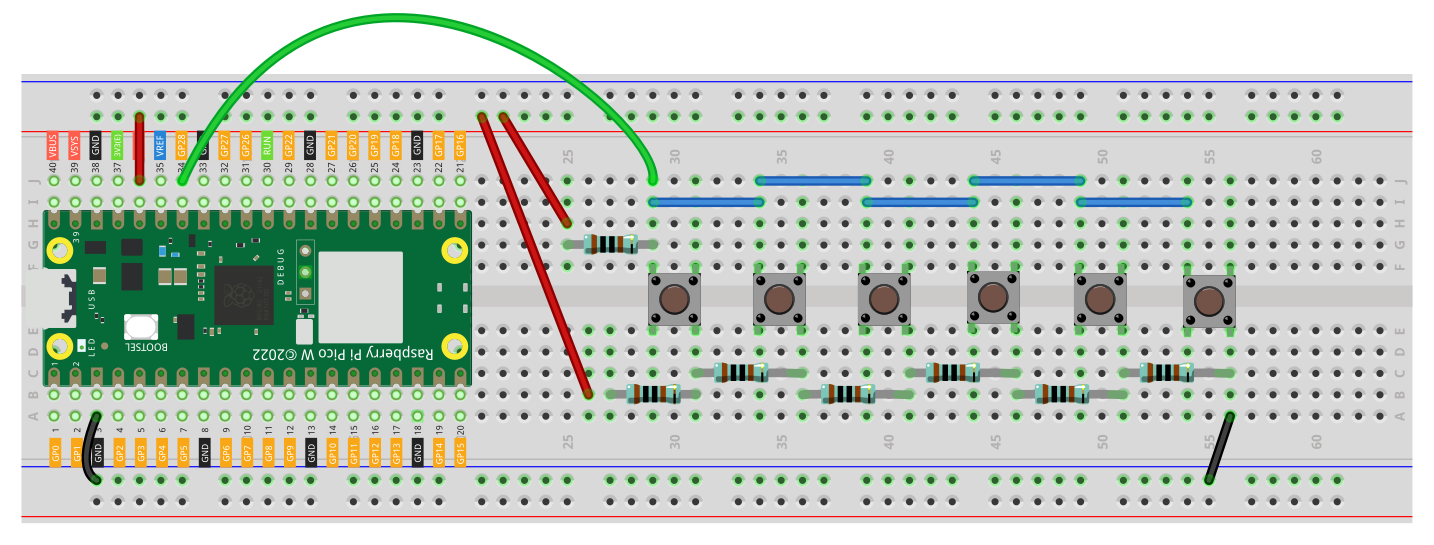
Example Setup
This tutorial assumes:
- buttons connect to
ADC2 ADC2is onGP28- only one button is pressed at a time
Example usage:
Basic ADC Read Test
Before trying to identify buttons, confirm that the Pico can read the analog value.
from machine import ADC, Pin
import utime

adc = ADC(Pin(28))   # ADC0 on GP26

while True:
    value = adc.read_u16()
    print(value)
    utime.sleep(0.2)
What to Do Here
- Run the script with no buttons pressed and note the value.
- Press each button one at a time.
- Write down the approximate ADC value for each button.
- Use those values to create threshold ranges.
Example ADC Readings
Your values will depend on your resistor choices, but an example might look like:
- no button ->
65535 - button 1 ->
52000 - button 2 ->
38000 - button 3 ->
22000 - button 4 ->
9000
Do not hardcode exact values unless you have tested them. Use ranges instead.
Example 1 - Detect Which Button Was Pressed
from machine import ADC, Pin
import utime

adc = ADC(Pin(28))

def get_button(value):
    if value > 60000:
        return "No button"
    elif 58000 <= value <= 60000:
        return "Button 1"
    elif 54000 <= value <= 57000:
        return "Button 2"
    elif 51000 <= value <= 53000:
        return "Button 3"
    elif 44000 <= value <= 47000:
        return "Button 4"
    elif 33000 <= value <= 37000:
        return "Button 5"
    elif 100 <= value <= 500:
        return "Button 6"

while True:
    value = adc.read_u16()
    button = get_button(value)
    print("ADC:", value, "->", button)
    utime.sleep(0.15)
Code Explanation
adc = ADC(Pin(28))
This configures GP28 as an analog input.
value = adc.read_u16()
This reads the analog input as a 16-bit number from 0 to 65535.
def get_button(value):
This helper function converts a raw ADC reading into a button label.
elif 58000 <= value <= 60000:
    return "Button 1"
Each button is identified by a range rather than one exact ADC value. That makes the code more stable when resistor values and supply voltage vary slightly.
Example 2 - Debounced Button Reader
If you print values too fast, the output may flicker or repeat too much. A simple debounce check helps.
from machine import ADC, Pin
import utime

adc = ADC(Pin(28))
last_button = "No button"

def get_button(value):
    if value > 60000:
        return "No button"
    elif 58000 <= value <= 60000:
        return "Button 1"
    elif 54000 <= value <= 57000:
        return "Button 2"
    elif 51000 <= value <= 53000:
        return "Button 3"
    elif 44000 <= value <= 47000:
        return "Button 4"
    elif 33000 <= value <= 37000:
        return "Button 5"
    elif 100 <= value <= 500:
        return "Button 6"
    return "Unknown"

while True:
    value = adc.read_u16()
    button = get_button(value)

    if button != last_button:
        print("Pressed:", button)
        last_button = button

    utime.sleep(0.1)
Tuning the Thresholds
This is the most important part of the project.
When you wire your actual resistor ladder:
- print the raw ADC values
- press each button several times
- note the minimum and maximum readings for each button
- create thresholds with safe spacing between them
For example, if one button reads from 34500 to 36000, you might define:
elif 34000 <= value <= 36500:
    return "Button 2"
Common Problems
Button values overlap
- choose resistor values with more separation
- measure the real ADC values again
- widen or tighten your thresholds
Readings jump around too much
- make sure the wiring is solid
- shorten jumper wires if possible
- add a small delay before reading again
- consider averaging a few ADC samples
Two buttons pressed at once
This method is usually intended for one-button-at-a-time input. Multiple simultaneous presses can create unexpected voltages.
No clear value when idle
Make sure your ladder includes a proper reference path so the ADC pin is not floating when no button is pressed.
Improvement Ideas
Once the basic version works, you can extend it with:
- averaging multiple ADC readings
- menu navigation on an LCD or OLED
- a handheld game controller
- a custom PCB with a resistor ladder keypad
- a project where buttons change LED effects or motor states
Summary
Using ADC for multiple button inputs is a clever way to save GPIO pins on the Raspberry Pi Pico. Instead of giving each button its own digital input, you use resistor values to generate different voltages and read them from one analog pin.
That makes this technique especially useful for:
- menu systems
- compact controllers
- small handheld devices
- projects where GPIO pins are limited
The most important part is not the exact resistor values. The important part is building a circuit where each button produces a clear, repeatable ADC range.