Tutorial 6 - Joystick
Introduction
The joystick module is a fun input device that works much like the analog sticks on a game controller.
It has two potentiometers for the X and Y axes, plus a push button that can be pressed by pressing down on the stick.
In this tutorial, we'll connect the joystick to the ESP32-S3 Pico and use MicroPython to read the values,
then build a simple example where the joystick controls the brightness of an LED using PWM.
YouTube Video
Components Needed
| Component | Quantity |
|---|---|
| ESP32-S3 Pico | 1 |
| USB-C Cable | 1 |
| Breadboard | 1 |
| Jumper Wires | Several |
| Joystick Module | 1 |
| LED + 330ohm Resistor | 1 |
Fritzing Diagram
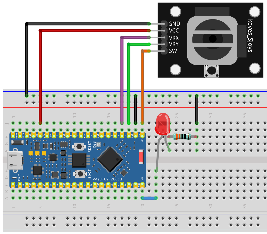
Connections:
- VRx (X-Axis) -> GPIO1 (ADC)
- VRy (Y-Axis) -> GPIO2 (ADC)
- SW (Button) -> GPIO42
- VCC -> 3.3V
- GND -> GND
For the LED example:
- LED Anode -> GPIO40 (PWM pin)
- LED Cathode -> GND (via 330ohm resistor)
Demo 1 - Reading Joystick Values
from machine import Pin, ADC
import utime

xAxis = ADC(Pin(1))
yAxis = ADC(Pin(2))
button = Pin(42, Pin.IN, Pin.PULL_UP)

while True:
    xValue = xAxis.read_u16()
    yValue = yAxis.read_u16()
    buttonValue = button.value()
    buttonStatus = "not pressed"

    if buttonValue == 0:
        buttonStatus = "pressed"

    print("X:", xValue, "Y:", yValue,
          "-- button value:", buttonValue,
          "status:", buttonStatus)
    utime.sleep(0.2)
Code Explanation (Block by Block)
1. Setup
xAxis = ADC(Pin(1))
yAxis = ADC(Pin(2))
button = Pin(42, Pin.IN, Pin.PULL_UP)
ADC(Pin(1))-> Reads analog values from X-axis.ADC(Pin(2))-> Reads analog values from Y-axis.Pin(42, Pin.IN, Pin.PULL_UP)-> Configures button with a pull-up resistor.
2. Reading values
xValue = xAxis.read_u16()
yValue = yAxis.read_u16()
buttonValue = button.value()
read_u16()returns a number between 0-65535 (joystick position).button.value()returns1(not pressed) or0(pressed).
3. Button logic
buttonStatus = "not pressed"
if buttonValue == 0:
    buttonStatus = "pressed"
- Simple
ifstatement to make button output human-readable.
4. Printing results
print("X:", xValue, "Y:", yValue, "-- button:", buttonStatus)
- Displays X, Y, and button state in the console.
Demo 2 - Controlling LED Brightness with Joystick
Now let's use the X-axis of the joystick to control LED brightness with PWM.
from machine import Pin, ADC, PWM
import utime

# Setup joystick X-axis
xAxis = ADC(Pin(1))

# Setup LED on GPIO40 with PWM
led = PWM(Pin(40))
led.freq(2000)   # 2 kHz PWM frequency

while True:
    # Read joystick X-axis (0-65535)
    xValue = xAxis.read_u16()

    # Map joystick value to PWM duty cycle (0-1023)
    brightness = int(xValue / 64)  # 65535 / 1023 ≈ 64

    led.duty(brightness)

    print("X:", xValue, "Brightness:", brightness)
    utime.sleep(0.1)
Code Explanation (Block by Block)
1. PWM setup
led = PWM(Pin(40))
led.freq(2000)
- Configures GPIO40 for PWM output.
freq(2000)sets PWM frequency to 2 kHz (good for LEDs).
2. Reading joystick
xValue = xAxis.read_u16()
- Returns a value 0-65535 depending on joystick tilt.
3. Mapping joystick to PWM
brightness = int(xValue / 64)
- PWM duty cycle for ESP32 ranges from 0-1023.
- Divide by 64 to scale 65535 down to 1023.
4. Setting LED brightness
led.duty(brightness)
- Updates LED brightness in real-time.
Summary
- The joystick has X, Y axes (analog) and a button (digital).
- You learned to read values and display them in the console.
- You also controlled an LED's brightness using PWM and the X-axis.
OK With this foundation, you can expand into games, menu navigation, or robotic controls with the joystick and ESP32-S3 Pico.