MCP3208 ADC Tutorial
Introduction
One limitation of the Raspberry Pi Pico is that it only has a small number of built-in analog input (ADC) pins. If your project needs to read more sensors, potentiometers, or variable voltages, you will quickly run out of inputs.
To solve this, we can use an external analog-to-digital converter like the MCP3208. This chip provides 8 additional analog channels and communicates with the Pico using the SPI protocol.
In this tutorial, you will learn how to:
Connect an MCP3208 to the Pico Read analog values using CircuitPython Expand your system by adding a second MCP3208
One of the key advantages of SPI is that it allows multiple devices to share the same communication lines. All MCP3208 chips can use the same clock and data pins, and the only connection that must be unique for each chip is the CS (Chip Select) pin.
This means you can easily scale your project from 8 inputs to 16, 24, or more with minimal changes.
Why Use an External ADC?
An external ADC is useful when:
- you need more analog inputs than the Pico has built in
- you want a dedicated analog input chip
- you are reading several potentiometers or sensors at once
- you want to expand a project without moving to a different microcontroller
What This Tutorial Covers
In this tutorial, you will learn:
- What the MCP3208 does
- How to wire it to the Pico with SPI
- How to install the CircuitPython libraries
- How to read two or more analog channels
- How to scale the values for real projects
Components Needed
| Component | Quantity |
|---|---|
| Raspberry Pi Pico or Pico W | 1 |
| MCP3208 | 1 or more |
| Breadboard | 1 |
| Jumper wires | Several |
| Joystick modules | 1 or more |
| USB cable | 1 |
Wiring for one MCP3208
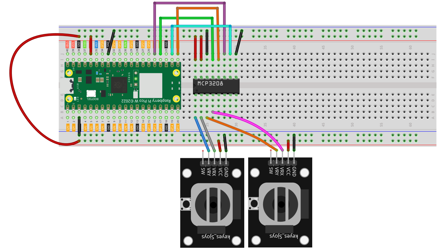
SCK -> GP18MISO -> GP16MOSI -> GP19CS -> GP17
Then connect your analog signals to:
CH0CH1CH2- and so on up to
CH7
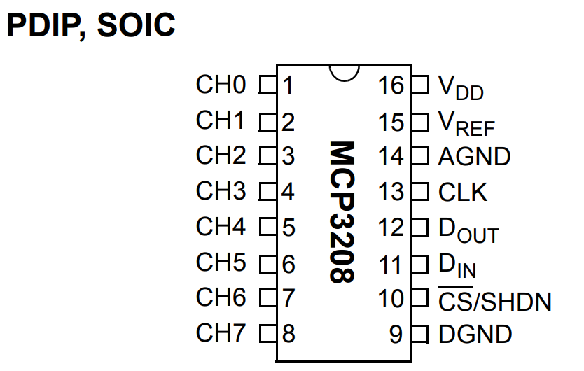
The pinout of the mcp3208
CircuitPython Libraries Needed
You will need:
adafruit_mcp3xxxadafruit_bus_device
These are normally copied into the lib folder on the CIRCUITPY drive.
If you are using the Adafruit CircuitPython bundle, copy the relevant library folders from the bundle into:
/lib
I am including the complete code here to download which you can copy everything and paste in the circuitpython flash drive.
Example Code
This is your current working example for the MCP3208:
import time
import board
import busio
import digitalio

import adafruit_mcp3xxx.mcp3208 as MCP
from adafruit_mcp3xxx.analog_in import AnalogIn

# SPI setup (your wiring)
spi = busio.SPI(clock=board.GP18, MISO=board.GP16, MOSI=board.GP19)

# Chip Select (your CS pin)
cs = digitalio.DigitalInOut(board.GP17)

# MCP3208 setup
mcp = MCP.MCP3208(spi, cs)

# Channels
ch0 = AnalogIn(mcp, MCP.P0)  # Channel 0
ch1 = AnalogIn(mcp, MCP.P1)  # Channel 1

print("Reading MCP3208 CH0 and CH1...")

while True:
    print("CH0:", ch0.value, " | CH1:", ch1.value)
    time.sleep(0.5)
Code Explanation
1. SPI Setup
spi = busio.SPI(clock=board.GP18, MISO=board.GP16, MOSI=board.GP19)
This creates the SPI bus used to talk to the ADC chip.
2. Chip Select
cs = digitalio.DigitalInOut(board.GP17)
The chip-select line tells the MCP3208 when the Pico is communicating with it.
3. Create the ADC Object
mcp = MCP.MCP3208(spi, cs)
This initializes the MCP3208 driver object using the SPI bus and chip-select pin.
4. Create Analog Channels
ch0 = AnalogIn(mcp, MCP.P0)
ch1 = AnalogIn(mcp, MCP.P1)
These represent channel 0 and channel 1 on the chip.
5. Read the Values
print("CH0:", ch0.value, " | CH1:", ch1.value)
This prints the current analog reading from both channels.
What Does .value Mean?
AnalogIn.value gives a scaled integer reading. In practice, it is convenient because you do not need to manually talk to SPI registers yourself. You just read the channel object.
For many hobby projects, this is enough to:
- compare sensor levels
- read potentiometer positions
- control brightness or speed
- monitor changing analog signals
Example 2 - Read More Channels
If you want to use more of the ADC chip, you can create more channels:
import time
import board
import busio
import digitalio

import adafruit_mcp3xxx.mcp3208 as MCP
from adafruit_mcp3xxx.analog_in import AnalogIn

spi = busio.SPI(clock=board.GP18, MISO=board.GP16, MOSI=board.GP19)
cs = digitalio.DigitalInOut(board.GP17)

mcp = MCP.MCP3208(spi, cs)

ch0 = AnalogIn(mcp, MCP.P0)
ch1 = AnalogIn(mcp, MCP.P1)
ch2 = AnalogIn(mcp, MCP.P2)
ch3 = AnalogIn(mcp, MCP.P3)

while True:
    print(
        "CH0:", ch0.value,
        "CH1:", ch1.value,
        "CH2:", ch2.value,
        "CH3:", ch3.value
    )
    time.sleep(0.5)
Example 3 - Read Potentiometers as Percentage
This is often easier to understand than raw ADC values.
import time
import board
import busio
import digitalio

import adafruit_mcp3xxx.mcp3208 as MCP
from adafruit_mcp3xxx.analog_in import AnalogIn

spi = busio.SPI(clock=board.GP18, MISO=board.GP16, MOSI=board.GP19)
cs = digitalio.DigitalInOut(board.GP17)

mcp = MCP.MCP3208(spi, cs)

ch0 = AnalogIn(mcp, MCP.P0)
ch1 = AnalogIn(mcp, MCP.P1)

while True:
    pct0 = (ch0.value / 65535) * 100
    pct1 = (ch1.value / 65535) * 100

    print("CH0: {:.1f}% | CH1: {:.1f}%".format(pct0, pct1))
    time.sleep(0.5)
Common Problems
No readings at all
- check
VDD,VREF,AGND, andDGND - confirm SPI wiring
- confirm the chip-select pin matches your code
Values do not change
- check whether your analog source is connected to the right channel
- confirm the sensor or potentiometer is powered correctly
- verify the channel number in code
Strange or unstable values
- check breadboard wiring
- make sure grounds are shared
- make sure the analog input is not floating
Wrong chip library
If the hardware is MCP3008 but the code imports mcp3208, the tutorial will be confusing. Match the library to the actual chip on your board.
Wiring Multiple MCP3208s
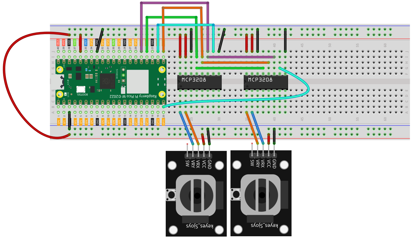
In this diagram we added a second MCP3208.
Both chips share the same SPI lines:
SCKMISOMOSI
The only connection that must be different for each chip is the CS pin.
Example:
- first
MCP3208->CS = GP17 - second
MCP3208->CS = GP15
This makes SPI a very convenient way to expand the number of analog inputs in a CircuitPython project.
Example 4 - Reading Two MCP3208s
Here is a simple example that reads two channels from each chip, giving you four analog inputs total.
import time
import board
import busio
import digitalio

import adafruit_mcp3xxx.mcp3208 as MCP
from adafruit_mcp3xxx.analog_in import AnalogIn

# SPI setup (shared)
spi = busio.SPI(clock=board.GP18, MISO=board.GP16, MOSI=board.GP19)

# Chip Select pins
cs1 = digitalio.DigitalInOut(board.GP17)  # First MCP
cs2 = digitalio.DigitalInOut(board.GP15)  # Second MCP (change if you used different pin)

# MCP3208 setup
mcp1 = MCP.MCP3208(spi, cs1)
mcp2 = MCP.MCP3208(spi, cs2)

# Channels from MCP #1
ch0 = AnalogIn(mcp1, MCP.P0)
ch1 = AnalogIn(mcp1, MCP.P1)

# Channels from MCP #2
ch2 = AnalogIn(mcp2, MCP.P0)
ch3 = AnalogIn(mcp2, MCP.P1)

print("Reading 2 MCP3208s (4 channels total)...")

while True:
    print(
        "MCP1 CH0:", ch0.value,
        "| MCP1 CH1:", ch1.value,
        "| MCP2 CH0:", ch2.value,
        "| MCP2 CH1:", ch3.value
    )
    time.sleep(0.5)
You can keep expanding this idea with more MCP3208 chips, as long as each one has its own chip-select pin.
Summary
An external ADC such as the MCP3208 is a great way to expand the analog input capability of the Raspberry Pi Pico in CircuitPython.
The key ideas are:
- use SPI
- use the correct
adafruit_mcp3xxxdriver - create one
AnalogInobject per channel - read multiple analog values from one external chip
That makes the Pico much more flexible when a project needs several analog inputs.